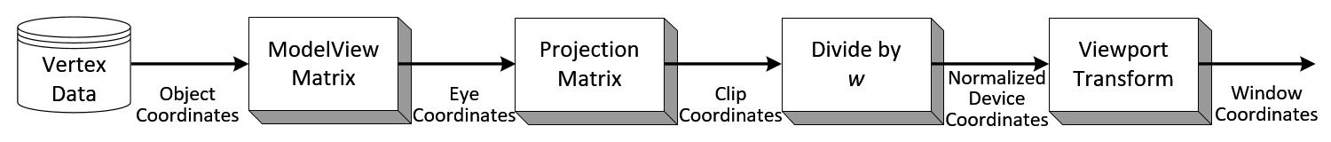
Showing posts with label Opengl. Show all posts

Monday, February 1, 2010

OpenGL Display List

OpenGL Display List


Display list is a group of OpenGL commands that have been stored (compiled) for later execution. Once a display list is created, all vertex and pixel data are evaluated and copied into the display list memory on the server machine. It is only one time process. After the display list has been prepared (compiled), you can reuse it repeatedly without re-evaluating and re-transmitting data over and over again to draw each frame. Display list is one of the fastest methods to draw static data because vertex data and OpenGL commands are cached in the display list and minimize data transmissions from the client to the server side. It means that it reduces CPU cycles to perform the actual data transfer.
Another important capability of display list is that display list can be shared with many clients, since it is server state.
For optimal performance, put matrix transforms, lighting and material calculation inside display list if possible, so OpenGL processes these expensive computations only once while display list is created, and stores the last results into the display list.
However, display list has a disadvantage. Once a display list is compiled, it cannot be modified later. If you need frequent changes or dynamic dataset, use Vertex Array or Vertex Buffer Object instead. Vertex Buffer Object can handle both static and dynamic dataset.
Note that not all OpenGL commands can be stored into the display lists. Since display list is a part of server state, any client state related commands cannot be placed in display list, for example, glFlush(), glFinish(), glRenderMode(), glEnableClientState(), glVertexPointer(), etc. And any command that returns a value cannot be stored in display list either, because the value should be returned to client side, not in display list, for example, glIsEnabled(), glGet*(), glReadPixels(), glFeedbackBuffer(), etc. If these commands are called in a display list, they are executed immediately.

Implementation

Using display list is quite simple. First thing to do is creating one or more of new display list objects with glGenLists(). The parameter is the number of lists to create, then it returns the index of the beginning of contiguous display list blocks. For instance, glGenLists() returns 1 and the number of display lists you requested was 3, then index 1, 2 and 3 are available to you. If OpenGL failed to create new display lists, it returns 0.
The display lists can be deleted by glDeleteLists() if they are not used anymore.
Second, you need to store OpenGL commands into the display list in between glNewList() and glEndList() block, prior to rendering. This process is called compilation. glNewList() requires 2 arguments; first one is the index of the display list that was returned by glGenLists(). The second argument is mode which specifies compile only or compile and also execute(render); GL_COMPILE, GL_COMPILE_AND_EXECUTE.
Up to now, preparation of display list has been done. Only thing you need to do is executing the display list with glCallList() or multiple display lists with glCallLists() every frame.
Take a look at the following code for a single display list first.
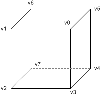
// create one display list
GLuint index = glGenLists(1);

// compile the display list, store a triangle in it
glNewList(index, GL_COMPILE);
    glBegin(GL_TRIANGLES);
    glVertex3fv(v0);
    glVertex3fv(v1);
    glVertex3fv(v2);
    glEnd();
glEndList();
...

// draw the display list
glCallList(index);
...

// delete it if it is not used any more
glDeleteLists(index, 1);
Note that only OpenGL commands between glNewList() and glEndList() will be recorded into a display list once and cached multiple times whenever it is called by glCallList().
In order to execute multiple display lists with glCallLists(), you need extra work to do. You need an array to store indices of display list that are only to be rendered. In other words, you can select and render only limited number of display lists from whole lists. glCallLists() requires 3 parameters; the number of list to draw, data type of index array, and pointer to the array.
Note that you don't have to specify the exact index of the display list into the array. You may specify the offset instead, then set the base offset with glListBase(). When glCallLists() is called, the actual index will be computed by adding the base and offset. The following code shows using glCallLists() and the detail explanation follows.
GLuint index = glGenLists(10);  // create 10 display lists
GLubyte lists[10];              // allow maximum 10 lists to be rendered

glNewList(index, GL_COMPILE);   // compile the first one
...
glEndList();

...// compile more display lists

glNewList(index+9, GL_COMPILE); // compile the last (10th)
...
glEndList();
...

// draw odd placed display lists only (1st, 3rd, 5th, 7th, 9th)
lists[0]=0; lists[1]=2; lists[2]=4; lists[3]=6; lists[4]=8;
glListBase(index);              // set base offset
glCallLists(5, GL_UNSIGNED_BYTE, lists);
For convenience, OpenGL provides glListBase() to specify the offset that is added to the display list indices when glCallLists() is executed.
In the above example, only 5 display lists are rendered; 1st, 3rd, 5th, 7th and 9th of display lists. Therefore the offset from index value is index+0, index+2, index+4, index+6, and index+8. These offset values are stored in the index array to be rendered. If the index value is 3 returned by glGenLists(), then the actual display lists to be rendered by glCallLists() are, 3+0, 3+2, 3+4, 3+6 and 3+8.
glCallLists() is very useful to display texts with the offsets corresponding ASCII value in the font.

Friday, January 29, 2010

OpenGL Transformation


Geometric data such as vertex positions and normal vectors are transformed via Vertex Operation andPrimitive Assembly operation in OpenGL pipeline before raterization process.
OpenGL vertex transformation

Object Coordinates

It is the local coordinate system of objects and is initial position and orientation of objects before any transform is applied. In order to transform objects, use glRotatef(), glTranslatef(), glScalef().

Eye Coordinates

It is yielded by multiplying GL_MODELVIEW matrix and object coordinates. Objects are transformed from object space to eye space using GL_MODELVIEW matrix in OpenGL. GL_MODELVIEWmatrix is a combination of Model and View matrices (Mview * Mmodel). Model transform is to convert from object space to world space. And, View transform is to convert from world space to eye space.
OpenGL eye coordinates
Note that there is no separate camera (view) matrix in OpenGL. Therefore, in order to simulate transforming the camera or view, the scene (3D objects and lights) must be transformed with the inverse of the view transformation. In other words, OpenGL defines that the camera is always located at (0, 0, 0) and facing to -Z axis in the eye space coordinates, and cannot be transformed. See more details of GL_MODELVIEW matrix in ModelView Matrix.
Normal vectors are also transformed from object coordinates to eye coordinates for lighting calculation. Note that normals are transformed in different way as vertices do. It is mutiplying the tranpose of the inverse of GL_MODELVIEW matrix by a normal vector. See more details in Normal Vector Transformation.
normal vector transformation

Clip Coordinates

It is after applying eye coordinates into GL_PROJECTION matrix. Objects are clipped out from the viewing volume (frustum). Frustum is used to determine how objects are projected onto screen (perspective or orthogonal) and which objects or portions of objects are clipped out of the final image. See more details of GL_PROJECTION matrix in Projection Matrix.
OpenGL clip coordinates

Normalized Device Coordinates (NDC)

It is yielded by dividing the clip coordinates by w. It is called perspective division. It is more like window (screen) coordinates, but has not been translated and scaled to screen pixels yet. The range of values is now normalized from -1 to 1 in all 3 axes.
OpenGL Normalized Device Coordinates

Window Coordinates (Screen Coordinates)

It is yielded by applying normalized device coordinates (NDC) to viewport transformation. The NDC are scaled and translated in order to fit into the rendering screen. The window coordinates finally are passed to the raterization process of OpenGL pipeline to become a fragment. glViewport()command is used to define the rectangle of the rendering area where the final image is mapped. And, glDepthRange() is used to determine the z value of the window coordinates. The window coordinates are computed with the given parameters of the above 2 functions;
glViewport(x, y, w, h);
glDepthRange(n, f);
OpenGL Window Coordinates
The viewport transform formula is simply acquired by the linear relationship between NDC and the window coordinates;


OpenGL Transformation Matrix
OpenGL Transform Matrix
OpenGL uses 4 x 4 matrix for transformations. Notice that 16 elements in the matrix are stored as 1D array in column-major order. You need to transpose this matrix if you want to convert it to the standard convention, row-major format.
OpenGL has 4 different types of matrices; GL_MODELVIEW,GL_PROJECTIONGL_TEXTURE, and GL_COLOR. You can switch the current type by using glMatrixMode() in your code. For example, in order to select GL_MODELVIEW matrix, use glMatrixMode(GL_MODELVIEW).

Model-View Matrix (GL_MODELVIEW)

GL_MODELVIEW matrix combines viewing matrix and modeling matrix into one matrix. In order to transform the view (camera), you need to move whole scene with the inverse transformation.gluLookAt() is particularly used to set viewing transform.
Columns of OpenGL ModelView matrix
4 columns of GL_MODELVIEW matrix
The 3 matrix elements of the rightmost column (m12,m13m14) are for the translation transformation,glTranslatef(). The element m15 is the homogeneous coordinate. It is specially used for projective transformation.
3 elements sets, (m0m1m2), (m4m5m6) and (m8,m9m10) are for Euclidean and affine transformation, such as rotation glRotatef() or scaling glScalef(). Note that these 3 sets are actually representing 3 orthogonal axes;
  • (m0m1m2)   : +X axis, left vector, (1, 0, 0) by default
  • (m4m5m6)   : +Y axis, up vector, (0, 1, 0) by default
  • (m8m9m10) : +Z axis, forward vector, (0, 0, 1) by default
We can directly construct GL_MODELVIEW matrix from angles or lookat vector without using OpenGL transform functions. Here are some useful codes to build GL_MODELVIEW matrix:
  • Angles to Axes
  • Lookat to Axes
Note that OpenGL performs matrices multiplications in reverse order if multiple transforms are applied to a vertex. For example, If a vertex is transformed by MA first, and transformed by MBsecond, then OpenGL performs MB x MA first before multiplying the vertex. So, the last transform comes first and the first transform occurs last in your code.
// Note that the object will be translated first then rotated
glRotatef(angle, 1, 0, 0);   // rotate object angle degree around X-axis
glTranslatef(x, y, z);       // move object to (x, y, z)
drawObject();

Projection Matrix (GL_PROJECTION)

GL_PROJECTION matrix is used to define the frustum. This frustum determines which objects or portions of objects will be clipped out. Also, it determines how the 3D scene is projected onto the screen. (Please see more details how to construct the projection matrix.)
OpenGL provides 2 functions for GL_PROJECTION transformation. glFrustum() is to produce a perspective projection, and glOrtho() is to produce a orthographic (parallel) projection. Both functions require 6 parameters to specify 6 clipping planes; leftrightbottomtopnear and farplanes. 8 vertices of the viewing frustum are shown in the following image.
OpenGL Perspective Frustum
OpenGL Perspective Viewing Frustum
The vertices of the far (back) plane can be simply calculated by the ratio of similar triangles, for example, the left of the far plane is;
OpenGL Orthographic Frustum
For orthographic projection, this ratio will be 1, so the leftright,bottom and top values of the far plane will be same as on the near plane.
You may also use gluPerspective() and gluOrtho2D() functions with less number of parameters. gluPerspective() requires only 4 parameters; vertical field of view (FOV), the aspect ratio of width to height and the distances to near and far clipping planes. The equivalent conversion from gluPerspective() to glFrustum() is described in the following code.
// This creates a symmetric frustum.
// It converts to 6 params (l, r, b, t, n, f) for glFrustum()
// from given 4 params (fovy, aspect, near, far)
void makeFrustum(double fovY, double aspectRatio, double front, double back)
{
    const double DEG2RAD = 3.14159265 / 180;

    double tangent = tan(fovY/2 * DEG2RAD);   // tangent of half fovY
    double height = front * tangent;          // half height of near plane
    double width = height * aspectRatio;      // half width of near plane

    // params: left, right, bottom, top, near, far
    glFrustum(-width, width, -height, height, front, back);
}

An example of an asymmetric frustum
However, you have to use glFrustum() directly if you need to create a non-symmetrical viewing volume. For example, if you want to render a wide scene into 2 adjoining screens, you can break down the frustum into 2 asymmetric frustums (left and right). Then, render the scene with each frustum.

Texture Matrix (GL_TEXTURE)

Texture coordinates (strq) are multiplied by GL_TEXTURE matrix before any texture mapping. By default it is the identity, so texture will be mapped to objects exactly where you assigned the texture coordinates. By modifying GL_TEXTURE, you can slide, rotate, stretch, and shrink the texture.
// rotate texture around X-axis
glMatrixMode(GL_TEXTURE);
glRotatef(angle, 1, 0, 0);

Color Matrix (GL_COLOR)

The color components (rgba) are multiplied by GL_COLOR matrix. It can be used for color space conversion and color component swaping. GL_COLOR matrix is not commonly used and is requiredGL_ARB_imaging extension.

Other Matrix Routines

glPushMatrix() : 
push the current matrix into the current matrix stack.
glPopMatrix() : 
pop the current matrix from the current matrix stack.
glLoadIdentity() : 
set the current matrix to the identity matrix.
glLoadMatrix{fd}(m) : 
replace the current matrix with the matrix m.
glLoadTransposeMatrix{fd}(m) : 
replace the current matrix with the row-major ordered matrix m.
glMultMatrix{fd}(m) : 
multiply the current matrix by the matrix m, and update the result to the current matrix.
glMultTransposeMatrix{fd}(m) : 
multiply the current matrix by the row-major ordered matrix m, and update the result to the current matrix.
glGetFloatv(GL_MODELVIEW_MATRIX, m) : 
return 16 values of GL_MODELVIEW matrix to m

Thursday, January 28, 2010

OpenGL Introduction

OpenGL Introduction

OpenGL is a software interface to graphics hardware. It is designed as a hardware-independent interface to be used for many different hardware platforms. OpenGL programs can also work across a network (client-server paradigm) even if the client and server are different kinds of computers. The client in OpenGL is a computer on which an OpenGL program actually executes, and the server is a computer that performs the drawings.

OpenGL uses the prefix gl for core OpenGL commands and glu for commands in OpenGL Utility Library. Similarly, OpenGL constants begin with GL_ and use all capital letters. OpenGL also uses suffix to specify the number of arguments and data type passed to a OpenGL call.
glColor3f(1, 0, 0);         // set rendering color to red with 3 floating numbers
glColor4d(0, 1, 0, 0.2);    // set color to green with 20% of opacity (double)
glVertex3fv(vertex);        // set x-y-z coordinates using pointer

State Machine

OpenGL is a state machine. Modes and attributes in OpenGL will be remained in effect until they are changed. Most state variables can be enabled or disabled with glEnable() or glDisable(). You can also check if a state is currently enabled or disabled with glIsEnabled(). You can save or restore a collection of state variables into/from attribute stacks using glPushAttrib() or glPopAttrib(). GL_ALL_ATTRIB_BITS parameter can be used to save/restore all states. The number of stacks must be at least 16 in OpenGL standard.
(Check your maximum stack size with glinfo.)
 
glPushAttrib(GL_LIGHTING_BIT);    // elegant way to change states because
    glDisable(GL_LIGHTING);       // you can restore exact previous states
    glEnable(GL_COLOR_MATERIAL);  // after calling glPopAttrib()
glPushAttrib(GL_COLOR_BUFFER_BIT);
    glDisable(GL_DITHER);
    glEnable(GL_BLEND);


glPopAttrib();                    // restore GL_COLOR_BUFFER_BIT
glPopAttrib();                    // restore GL_LIGHTING_BIT

glBegin() and glEnd()

In order to draw geometric primitives (points, lines, triangles, etc) in OpenGL, you can specify a list of vertex data between glBegin() and glEnd(). This method is called immediate mode. (You may draw geometric primitives using other methods such as vertex array.)
glBegin(GL_TRIANGLES);
    glColor3f(1, 0, 0);     // set vertex color to red
    glVertex3fv(v1);        // draw a triangle with v1, v2, v3
    glVertex3fv(v2);
    glVertex3fv(v3);
glEnd();
There are 10 types of primitives in OpenGL; GL_POINTS, GL_LINES, GL_LINE_STRIP, GL_LINE_LOOP, GL_TRIANGLES, GL_TRIANGLE_STRIP, GL_TRIANGLE_FAN, GL_QUADS, GL_QUAD_STRIP, and GL_POLYGON.

glFlush() & glFinish()

Similar to computer IO buffer, OpenGL commands are not executed immediately. All commands are stored in buffers first, including network buffers and the graphics accelerator itself, and are awaiting execution until buffers are full. For example, if an application runs over the network, it is much more efficient to send a collection of commands in a single packet than to send each command over network one at a time.
glFlush() empties all commands in these buffers and forces all pending commands will to be executed immediately without waiting buffers are full. Therefore glFlush() guarantees that all OpenGL commands made up to that point will complete executions in a finite amount time after calling glFlush(). And glFlush() does not wait until previous executions are complete and may return immediately to your program. So you are free to send more commands even though previously issued commands are not finished.
glFinish() flushes buffers and forces commands to begin execution as glFlush() does, but glFinish() blocks other OpenGL commands and waits for all execution is complete. Consequently, glFinish() does not return to your program until all previously called commands are complete. It might be used to synchronize tasks or to measure exact elapsed time that certain OpenGL commands are executed.

glVertexArray Explained

Instead you specify individual vertex data in immediate mode (between glBegin() and glEnd() pairs), you can store vertex data in a set of arrays including vertex coordinates, normals, texture coordinates and color information. And you can draw geometric primitives by dereferencing the array elements with array indices.
Take a look the following code to draw a cube with immediate mode.
Each face needs 4 times of glVertex*() calls to make a quad, for example, the quad at front is v0-v1-v2-v3. A cube has 6 faces, so the total number of glVertex*() calls is 24. If you also specify normals and colors to the corresponding vertices, the number of function calls increases to 3 times more; 24 of glColor*() and 24 of glNormal*().
The other thing that you should notice is the vertex "v0" is shared with 3 adjacent polygons; front, right and up face. In immediate mode, you have to provide the shared vertex 3 times, once for each face as shown in the code.
glBegin(GL_QUADS);      // draw a cube with 6 quads
    glVertex3fv(v0);    // front face
    glVertex3fv(v1);
    glVertex3fv(v2);
    glVertex3fv(v3);

    glVertex3fv(v0);    // right face
    glVertex3fv(v3);
    glVertex3fv(v4);
    glVertex3fv(v5);

    glVertex3fv(v0);    // up face
    glVertex3fv(v5);
    glVertex3fv(v6);
    glVertex3fv(v1);

    ...                 // draw other 3 faces

glEnd();
Using vertex arrays reduces the number of function calls and redundant usage of shared vertices. Therefore, you may increase the performance of rendering. Here, 3 different OpenGL functions are explained to use vertex arrays; glDrawArrays(), glDrawElements() and glDrawRangeElements(). Although, better approach is using vertex buffer objects (VBO) or display lists.

Initialization

OpenGL provides glEnableClientState() and glDisableClientState() functions to activate and deactivate 6 different types of arrays. Plus, there are 6 functions to specify the exact positions(addresses) of arrays, so, OpenGL can access the arrays in your application.
  • glVertexPointer():  specify pointer to vertex coords array
  • glNormalPointer():  specify pointer to normal array
  • glColorPointer():  specify pointer to RGB color array
  • glIndexPointer():  specify pointer to indexed color array
  • glTexCoordPointer():  specify pointer to texture cords array
  • glEdgeFlagPointer():  specify pointer to edge flag array
Each specifying function requires different parameters. Please look at OpenGL function manuals. Edge flags are used to mark whether the vertex is on the boundary edge or not. Hence, the only edges where edge flags are on will be visible if glPolygonMode() is set with GL_LINE.
Notice that vertex arrays are located in your application(system memory), which is on the client side. And, OpenGL on the server side gets access to them. That is why there are distinctive commands for vertex array; glEnableClientState() and glDisableClientState() instead of using glEnable() and glDisable().

glDrawArrays()

glDrawArrays() reads vertex data from the enabled arrays by marching straight through the array without skipping or hopping. Because glDrawArrays() does not allows hopping around the vertex arrays, you still have to repeat the shared vertices once per face.
glDrawArrays() takes 3 arguments. The first thing is the primitive type. The second parameter is the starting offset of the array. The last parameter is the number of vertices to pass to rendering pipeline of OpenGL.
For above example to draw a cube, the first parameter is GL_QUADS, the second is 0, which means starting from beginning of the array. And the last parameter is 24: a cube requires 6 faces and each face needs 4 vertices to build a quad, 6 × 4 = 24.

GLfloat vertices[] = {...}; // 24 of vertex coords
...
// activate and specify pointer to vertex array
glEnableClientState(GL_VERTEX_ARRAY);
glVertexPointer(3, GL_FLOAT, 0, vertices);

// draw a cube
glDrawArrays(GL_QUADS, 0, 24);

// deactivate vertex arrays after drawing
glDisableClientState(GL_VERTEX_ARRAY);
As a result of using glDrawArrays(), you can replace 24 glVertex*() calls with a single glDrawArrays() call. However, we still need to duplicate the shared vertices, so the number of vertices defined in the array is still 24 instead of 8. glDrawElements() is the solution to reduce the number of vertices in the array, so it allows transferring less data to OpenGL.
The size of vertex coordinates array is now 8, which is exactly same number of vertices in the cube without any redundant entries.
Note that the data type of index array is GLubyte instead of GLuint or GLushort. It should be the smallest data type that can fit maximum index number in order to reduce the size of index array, otherwise, it may cause performance drop due to the size of index array. Since the vertex array contains 8 vertices, GLubyte is enough to store all indices.

Different normals at shared vertex
Another thing you should consider is the normal vectors at the shared vertices. If the normals of the adjacent polygons at a shared vertex are all different, then normal vectors should be specified as many as the number of faces, once for each face.

For example, the vertex v0 is shared with the front, right and up face, but, the normals cannot be shared at v0. The normal of the front face is n0, the right face normal is n1 and the up face is n2. For this situation, the normal is not the same at a shared vertex, the vertex cannot be defined only once in vertex array any more. It must be defined multiple times in the array for vertex coordinates in order to match the same amount of elements in the normal array.

glDrawRangeElements()

Like glDrawElements(), glDrawRangeElements() is also good for hopping around vertex array. However, glDrawRangeElements() has two more parameters (start and end index) to specify a range of vertices to be prefetched. By adding this restriction of a range, OpenGL may be able to obtain only limited amount of vertex array data prior to rendering, and may increase performance.
The additional parameters in glDrawRangeElements() are start and end index, then OpenGL prefetches a limited amount of vertices from these values: end - start + 1. And the values in index array must lie in between start and end index. Note that not all vertices in range (start, end) must be referenced. But, if you specify a sparsely used range, it causes unnecessary process for many unused vertices in that range.
GLfloat vertices[] = {...};     // 8 of vertex coords
GLubyte indices[] = {0,1,2,3,   // 24 of indices
                     0,3,4,5,
                     0,5,6,1,
                     1,6,7,2,
                     7,4,3,2,
                     4,7,6,5};
...
// activate and specify pointer to vertex array
glEnableClientState(GL_VERTEX_ARRAY);
glVertexPointer(3, GL_FLOAT, 0, vertices);

// draw first half, range is 6 - 0 + 1 = 7 vertices
glDrawRangeElements(GL_QUADS, 0, 6, 12, GL_UNSIGNED_BYTE, indices);

// draw second half, range is 7 - 1 + 1 = 7 vertices
glDrawRangeElements(GL_QUADS, 1, 7, 12, GL_UNSIGNED_BYTE, indices+12);

// deactivate vertex arrays after drawing
glDisableClientState(GL_VERTEX_ARRAY);
You can find out maximum number of vertices to be prefetched and the maximum number of indices to be referenced by using glGetIntegerv() with GL_MAX_ELEMENTS_VERTICES and GL_MAX_ELEMENTS_INDICES.
Note that glDrawRangeElements() is available OpenGL version 1.2 or greater.